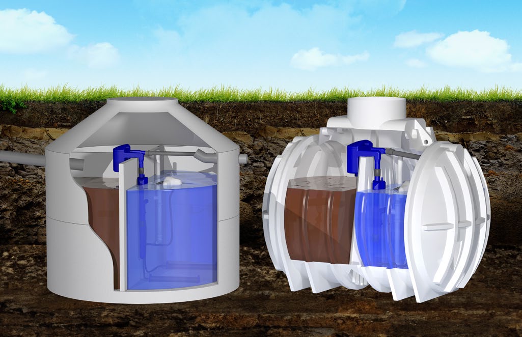
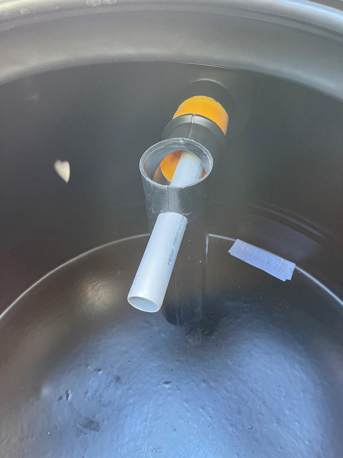
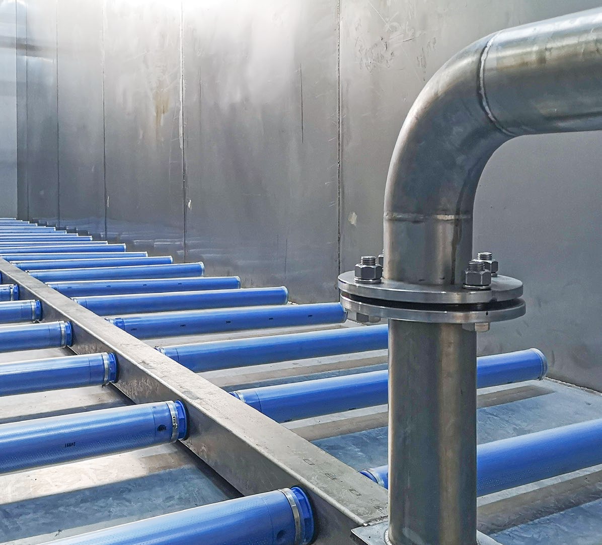
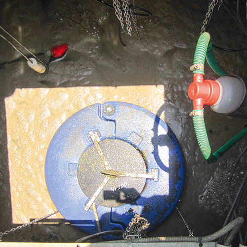
This installation uses two locally manufactured polyethylene (PE) tanks. PUROO® Z provides the treatment equipment for installation in empty tanks. Tank options and configurations depend on the project and ATB's requirements. Explore the PUROO® Z configuration
Choose a product family to follow the treatment process and identify its components in the manufacturer's diagrams.
PUROO · OPERATING PRINCIPLE
A cycle that responds to the water level.
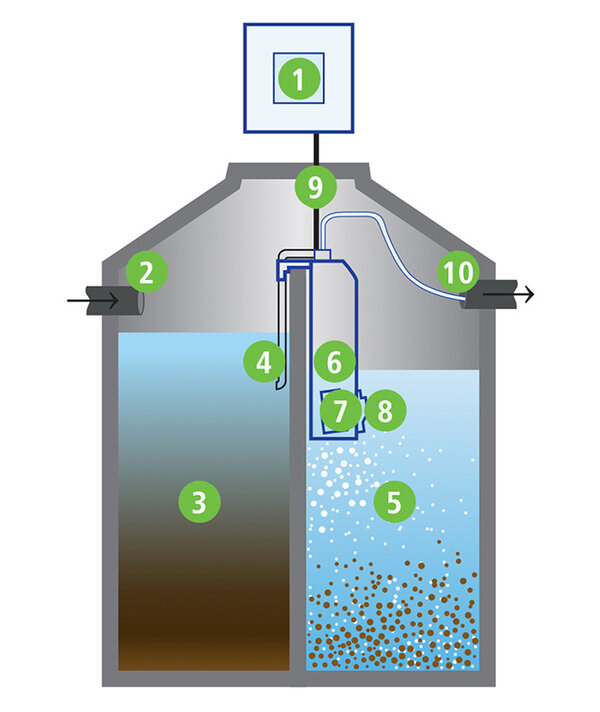
The pretreatment chamber works together with the biological treatment chamber, a sequencing batch reactor (SBR). Microorganisms in the activated sludge break down organic matter. The water level determines when settling and discharge begin.
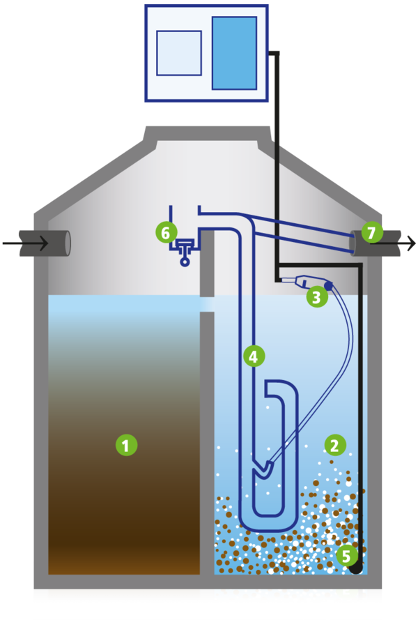
ATB WATER diagram. Numbers identify components, not successive treatment stages.Identify the components in the diagram +
Pretreatment
SBR chamber
Mechanical float
Airlift pump
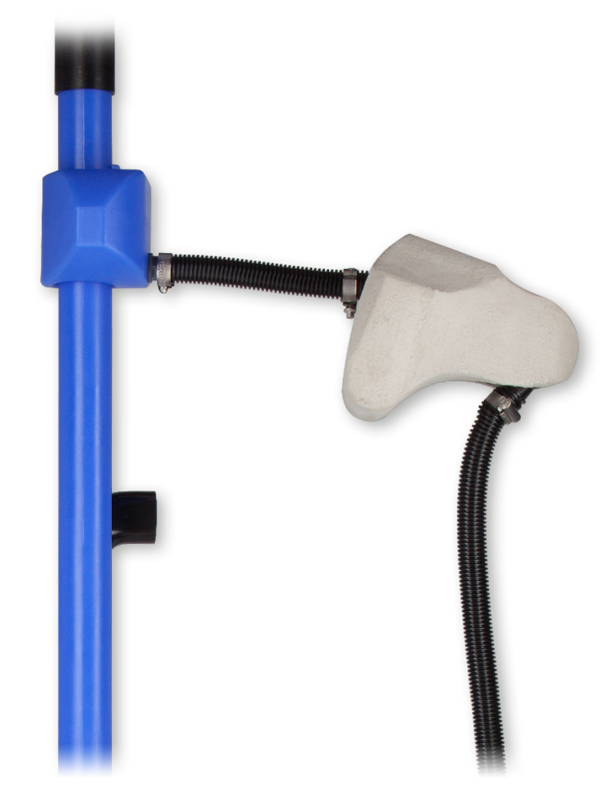
Tubular diffuser
Outlet valve
Treated effluent outlet
01
Inlet and pretreatment.
Wastewater passes through pretreatment and into the connected SBR chamber. Diagram references: 1 and 2.
02
Biological aeration.
The diffuser supplies air at intervals, supporting treatment by microorganisms suspended in the wastewater. Diagram references: 2 and 5.
03
Level-triggered activation.
As the water level rises, the mechanical float activates the airlift pump. Short pulses return sludge to the pretreatment chamber. Diagram references: 3, 4 and 6.
04
Settling.
During a settling period, sludge settles out, leaving clarified water above it. Diagram reference: 2.
05
Discharge and restart.
The airlift pump discharges the treated effluent. At the minimum water level, the air supply returns to the diffuser and a new cycle begins. Diagram references: 4, 6, 7 and 5.
The process shown uses air to transfer water, without a submersible electric pump or solenoid valves.
PUROO Complete uses the same SBR process and water-level control as PUROO, with added aeration in the first chamber. The additional oxygen supports sludge stabilization and may reduce sludge volume and odors.
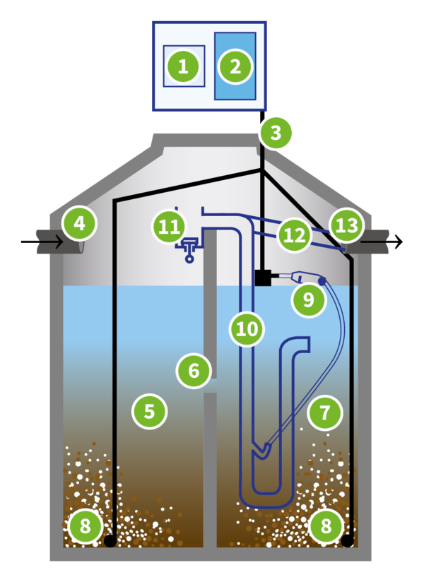
ATB WATER diagram. Numbers identify components, not successive treatment stages.Identify the components in the diagram +
Automatic control
Diaphragm blower
Air hose
Inlet
First chamber
Partition with opening
Second chamber
Tubular diffusers
Float valve
Airlift pump
Intermediate tank and sampling point
Clarified water pipe
Outlet
01
Aerated first chamber.
Wastewater enters the first chamber, where diffusers supply oxygen and biological treatment begins. Diagram references: 4, 5 and 8.
02
Transfer to the second chamber.
An opening in the partition connects the two chambers. Treatment continues in the second chamber. Diagram references: 6 and 7.
03
Aeration and level-based control.
A blower supplies air to the system. The float and airlift pump help control the cycle in response to the volume of incoming wastewater. Diagram references: 2, 3, 8, 9 and 10.
04
Separation and discharge.
After settling, the airlift pump discharges clarified water through the outlet assembly. Diagram references: 7, 10, 11, 12 and 13.
Aeration in the first chamber does not eliminate the need for maintenance or sludge removal when required.
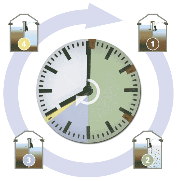
Wastewater first collects in the pretreatment chamber, where some solids settle. It then enters the SBR chamber for a cycle of filling, biological treatment, settling and discharge.
Official ATB WATER diagram. Numbers 1–4 correspond to the phases described.
01
Filling.
Wastewater collected in the pretreatment chamber is transferred to the treatment chamber.
02
Biological treatment.
Alternating periods of mixing, aeration and rest allow microorganisms in the activated sludge to treat the wastewater.
03
Settling.
Activated sludge settles to the bottom, leaving clarified water above it.
04
Discharge.
Clarified water is pumped to the system outlet.
The configuration described by ATB runs three eight-hour cycles per day, with six hours of treatment per cycle. Equipment and settings must be confirmed for the selected model and system capacity.
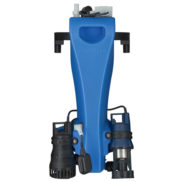
View an AQUAMAX cutaway +
This configuration uses a submersible pump and aerator. Other versions use blower-fed aeration, so this diagram does not represent every model. The animation on this page shows AQUAMAX BASIC specifically.
These diagrams illustrate operating principles and example configurations. System selection, maintenance, effluent discharge or reuse, and any additional treatment depend on the project and local requirements.
DE
GERMAN ENGINEERING · DOCUMENTED PERFORMANCE
German engineering. Documented performance.
Based in Porta Westfalica, Germany, ATB WATER has developed decentralized wastewater treatment technology since 1999. Engineering, system configuration and maintenance are tailored to each project. Tank materials and construction are specified for each installation.
The Declaration of Performance under EN 12566-3:2005+A2:2013 identifies PIA GmbH in Aachen, notified body NB1739, for the treatment-efficiency assessment.
The declaration applies to PUROO Complete and its tested configuration. It does not automatically extend to standard PUROO or AQUAMAX.
The approval covers PUROO Complete and PUROO Z Complete retrofit kits for wastewater treatment systems serving 4 to 50 population equivalents (PE), effluent class D.
This retrofit approval has a different scope from the CE declaration for systems serving up to 16 population equivalents. Check the configuration and supporting documents when selecting a system.
For these three parameters, the declaration reports concentrations below the limits in RTS Table 2. The figures describe the tested configuration's performance. They are neither universal limits under EN 12566-3 nor guaranteed results for every installation.
All values are in mg/L. The ATB declaration uses “SS” for suspended solids, shown here as TSS. This is not a measure of settleable solids.
PUROO Complete results and the cited Salvadoran limits
Parameter
Declared performance Tested configuration
RTS limit Table 2
BOD₅
9
60
COD
38
150
Total suspended solids · TSS
15
60
Conditions, criteria and scope of the evidence +
PUROO Complete declaration.
The manual and declaration dated June 15, 2026, cover domestic wastewater treatment for up to 16 population equivalents. The tested load was 0.29 kg BOD₅/day, with a rated load of 0.36 kg/day and a rated flow of 0.9 m³/day. These results cannot be applied to other system sizes, loads or effluents without further evaluation.
The declaration also reports 1.9 mg/L of ammoniacal nitrogen and 10 mg/L of total nitrogen. RTS Table 2 does not set numerical limits for these parameters. Other project-specific requirements may apply.
DIBt approval criteria.
The approval criteria include BOD₅ ≤15 mg/L and COD ≤75 mg/L for a 24-hour composite sample. These values are numerically lower than the respective limits of 60 and 150 mg/L in RTS Table 2, but the protocols and conditions differ. These are approval criteria, not the measured results shown above.
The published approval is valid through October 6, 2027. Review the approval and its conditions when preparing the project specification.
This comparison refers to Table 2 of RTS 13.05.01:24 for domestic wastewater (classified as “ordinary” under the RTS) discharged into a receiving environment. Compliance depends on flow rate, wastewater load, system configuration, operation, sampling and the required authorizations. Individual domestic wastewater systems that use soil infiltration are outside the scope of this RTS. Reuse requires specific evaluation and authorization. Non-domestic wastewater (the “special” category) and sewer discharges are subject to separate requirements.
A biological wastewater treatment system for small installations, using airlift transfer and mechanical airflow control. Suitable for new installations and retrofits in existing tanks.
View specifications and documents +
Reference capacity
1–16 population equivalents (PE)
Treatment
Activated sludge in a sequencing batch reactor (SBR)
Water transfer
Airlift pumping
Configuration
Pretreatment followed by an SBR chamber
Mounting
Type M mounts on a partition; type Z fits tanks without a mounting partition
Reference energy consumption
Approximately 30 kWh per connected person per year, according to the manufacturer
PUROO Complete aerates both the first chamber and the treatment chamber. This supports sludge stabilization and limits gas formation from anaerobic decomposition.
View specifications and documents +
Reference capacity
1–16 population equivalents (PE)
Treatment
SBR with both chambers aerated
Water transfer
Airlift pumping
Applications
New installations and retrofitting existing systems
A treatment unit suspended from chains for tanks without a supporting partition. Versions are available for small households and installations with higher wastewater loads.
BASIC and CLASSIC Z use submersible aerators. CLASSIC ZB and PRO G ZB use blowers and diffusers. PUROO uses airlift transfer. AQUAMAX pumping and aeration equipment depends on the model.
03 / AQUAMAX PROFESSIONAL
Treatment at a larger scale.
Systems sized for variable flows, commercial facilities and community applications.
AQUAMAX PROFESSIONAL
AQUAMAX PRO G Z
1–16 PE and 17–50 PE
A system for variable flows and commercial applications, with a separate flow-equalization chamber and a pump that feeds the reactor.
A PRO G variant with blower-and-diffuser aeration, sized according to flow, load and tank geometry.
View specifications and documents +
Documented capacity
1–125 PE, depending on configuration
Aeration
Blowers and tubular diffusers
Control
ATBcontrol 4 Connect
This capacity applies to PRO G ZB, as documented in February 2026. The general PRO G webpage lists a different limit. Confirm the exact model and configuration for your project.
Modular SBR treatment systems for hotels, commercial facilities, residential developments and small communities. Modules can be combined to meet each project's requirements.
View specifications and documents +
Published range
50–1,000 PE
Published flow rate
Up to 150 m³/day
Aeration
Options with a surface aerator or diffusers and blower
Custom-designed wastewater treatment systems for municipal, tourism and industrial applications, with project-specific engineering from pretreatment through sludge management.
A containerized wastewater treatment system using SBR or MBBR, depending on the project. The design can incorporate additional treatment stages and be evaluated for parallel operation.
View specifications and documents +
Available technology
SBR or MBBR
Published flow rate
Up to 150 m³/day; higher flows through parallel treatment lines
Biological stages
Nitrification, denitrification and secondary clarification, depending on configuration
Installation
Site-built pretreatment or pretreatment integrated into containers, depending on scope
Options must be assessed for the selected model. Effluent reuse and discharge require an appropriate engineering design and compliance with local regulations.
For treatment capacity, PE means population equivalent, a measure of design load rather than a guaranteed number of residents served. There is no universal conversion from PE to flow rate. For tank materials, PE means polyethylene. Published capacities describe the manufacturer's available configurations. System selection, availability, tank volume and electrical requirements must be confirmed for each project. References to EN standards, CE marking or DIBt approval do not replace local permits or regulatory requirements.
01 / TECHNOLOGY UP CLOSE
Equipment and installation.
Decentralized biological wastewater treatment with PUROO and AQUAMAX for homes, businesses and communities. Treatment technologies and any additional stages are selected to suit each application.
Selection, availability and technical references +
Selection and availability depend on the application. Confirm specifications, configuration and local regulatory requirements before choosing equipment.
Correct sizing starts with your site.
System sizing takes account of daily flow, organic load, changes in occupancy and discharge requirements. Share your site's operating conditions so we can discuss a suitable system.
Tell us your business activity, location and what you need to resolve. For an existing system, include the model and the issue you have noticed. For a new system, share its intended use and any known flow rate or capacity.

 Declared conformity